AI for turbulent boundary layers
Transportation by aircrafts is responsible for a considerable amount of the global greenhouse gas emissions. Although aircraft gas turbines have become continuously more efficient, there is an increasing interest of airline companies and manufacturers to enable of air traffic growth without increasing CO₂ emissions. In the past, passive drag reduction concepts in form of riblets were explored to lower the drag of an aircraft. The concept of riblets was developed after analysing the effect of microstructures found in shark skins. These microstructures reduce friction drag, which is one component of the aircraft drag responsible for up to 50 percent of the total drag for standard aircrafts. Friction drag is generated in the boundary layer, i.e., a thin fluid layer in which the velocity changes from the free stream to the surface velocity, due to the viscosity of a fluid.
In flows at high Reynolds number, e.g. for passenger aircrafts in cruise flight, the boundary layers are usually in the turbulent state. That is, the fluid in the boundary layer exhibits a seemingly chaotic and unpredictable behaviour. The turbulence in the boundary layers increases the friction drag on the skin of the wings and fuselage due to the enhanced mixing of momentum, which is why there is a large interest to manipulate the turbulence in the boundary layers with the goal of drag reduction.
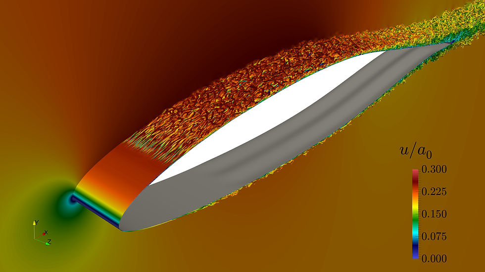
Figure 1: Travelling surface waves on a DRA2303 airfoil reducing the friction drag and increasing the lift.
In this use case od RAISE, a recent approach of active surface movement is applied to a turbulent boundary layer. In general, the flat surface is deformed to the shape of a sine-wave of low amplitude and this wavy surface is then continuously transformed such that the crests and valleys of the surface are constantly moving in the spanwise direction, i.e., a direction perpendicular to the main flow direction. The generation of these spanwise travelling waves requires the surface to execute only a movement in wall normal direction, in the same way as the stadium waves during a soccer game. The goal of this use case is the identification of optimal actuation parameters that lower the total friction drag the surface experiences. The principle mode of operation can be observed in the video below, where turbulent structures above the actuated wall are visualized. The interaction of the oscillating wall with the boundary layer modifies the turbulent flow structures. Dependent on the wave parameters, the skin-friction drag reduces by up to 30 percent.
Figure 2: Manipulated turbulent boundary layer. Visualization of the turbulent flow structures over the actuated surface.
Since there are several parameters controlling the wall actuation, i.e., the wave length, wave amplitude and speed, which have to be adapted to the local boundary layer state, the determination of actuation parameters which minimize drag is not trivial. Therefore, machine learning methods such as the Cluster-Based Network Model (CBNM) will be used for the identification of optimal solutions in the multidimensional parameter space. Such models will be applied to individual predictions, which are based on the large eddy simulation of the turbulent flow field. Since such simulations are computationally expensive physics based deep learning (PIDL) and transfer learning (TL) methods will be applied, which are novel approaches that help to tackle the scarcity of training data. Additionally, pre-trained networks are used from similar tasks, e.g., networks are trained to predict and/or detect similar turbulent flow features with results from less expensive simulations.
These artificial intelligence (AI) tools will be used to analyze the effect of the modified near-wall turbulent structures and to identify relationships to drag reduction. Additionally, the noise generation of the turbulent boundary layer flow passing over the trailing edge of the airfoil will be assessed, to understand the effect of the surface actuation on the trailing edge noise. To avoid I/O of large data sets, in-situ processing of the solution data is implemented in cooperation with the project partner FZJ.
Institute of Aerodynamics, RWTH Aachen
Wüllnerstraße 5a, D-52062 Aachen (Germany)
e-mail: office [@] aia.rwth-aachen.de
www.aia.rwth-aachen.de